This
inverter uses PWM (
Pulse Width Modulator) with type
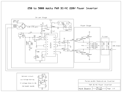
IC SG3524. IC serves as a oscillator 50Hz, as a regulator of the desired output voltage. Input power ranging from
250W up to
5000W output and has. Following a series
INVERTER 5000W with PWM (Pulse Width Modulator).
 |
Schematic Inverter 5000W with PWM (Pulse Width Modulator) |
 |
Layout PCB Inverter 5000W with PWM (Pulse Width Modulator) |
below is the output power settings that can be issued by this inverter:
DC voltage and Transformer "T2" winding recommendation:
Winding Power Supply12VDC 750W P: 24V "12-0-12" / S: 220V1500W 24VDC P: 48V "24-0-24" / S: 220V2250w 36VDC P: 72V "36-0-36" / S: 220V3000w 48VDC P: 96V "48-0-48" / S: 220V3750w 60VDC P: 120V "60-0-60" / S: 220V4500w 72VDC P: 144V "72-0-72" / S: 220V5250w 84VDC P: 168V "84-0-84" / S: 220VTransformer used is the transformer CT
R1 serves to regulate the voltage to
220v inverterR2 serves to regulate the inverter output frequency of 50 or 60 Hz (as appropriate)
Related Posts :
3V to High voltage inverterInverter circuit on basic of really taking a series of mosquito racket, a racket in which these mosq… Read More...
Mosfet Snubber Flyback Converter CircuitMosfet Snubber Circuit in Flyback Converter , Typical flyback convertor with drain clamping cir… Read More...
Simple Inverter Circuit from 12 V up to 120V elevatedThis is a simple 120 V : 24 V , center - tapped (CT) control transformer and four additional compone… Read More...
6V to 220V inverter schematicCircuit schematic above is one of the voltage inverter circuit, starting from 6-Volt input on the DC… Read More...
3V to 40 Volt DC Converter CircuitSwitching regulator subsystems intended for use as dc to dc converters. 3V to 40 Volt DC Converter c… Read More...
12V to 220V Inverter Schematics12V to 220V Inverter Circuit Diagrams, Even though today’s electrical appliances are increasingly of… Read More...
6 to 15 Volt DC ConverterA very efficient 6V to 15V DC to DC converter using LM2585 is publicized at this time. LM2585 is a m… Read More...
12V to +/- 20V DC Converter Circuit100 Watt 12V to +/- 20V DC Converter CircuitDC To DC Converter circuit used to be an convert v… Read More...
DC- DC Converter 12V to 24VThis simple circuit is a DC-DC converter that converting up 12V source to a 24V. It can be used to r… Read More...
Inverter 12V to 115V with 25 W power outputLow power inverter schematic are only use 9 components , one of which IC 556 , TIP120 NPN Darlington… Read More...
Simple Inverter circuit with IC556 timer chipThis circuit is low power inverter , in this circuit only save a few components, about 9 parts. Volt… Read More...
1000W Mosfet Power InverterThis 1000W Mosfet Power Inverter motivation provide a very unwavering “settle Wave” Output Vol… Read More...
Emergency Power Generator SourceNearby are many period as soon as even more power generator is looked-for, but not free. If an outle… Read More...
6 to 12 Volt ConverterBelow its a converter circuit voltage from 6 Volt to 12 Volt DC.6 Volt to 12 Volt DCPart List :R1, R… Read More...
Simple Inverter with Two TransistorsThe series below is a simple inverter circuit that will change the voltage of 12v dc to 220v ac, wit… Read More...
Frequency to Voltage Converter CircuitIC LM2917 Frequency to Voltage ConverterIC LM2917 IC chip is designed specifically as a Frequency to… Read More...
USB Voltage Converter 5V to 12VThis is a 5Volt to 12Volt DC-DC step-up (boost) converter circuitry with the intention of is especia… Read More...
Converter with 2N3055 transistorsThis plain converter using a Zener diode and a transistor into a 9V DC 12V DC battery power to the m… Read More...
Inverter 5000 Watt PWMThis inverter uses PWM (Pulse Width Modulator) with type IC SG3524. IC serves as a oscillator 50Hz, … Read More...
10Mhz to 1 MHz Frequency Converter10Mhz to 1 MHz Frequency Converter CircuitPart ListIC1 7404 = 1IC2 7490A = 1R 1 K = 2R 3.3 K = 1C Tr… Read More...
0 Response to "Inverter 5000 Watt PWM"
Post a Comment